The next step in fitting the slats is to use the holding and measuring jigs I built in the last post to measure the distance between the rear legs at each mortise as well as record the angle for the slat tenon shoulder. Those measurements are transferred to the slat blank and become the basis for laying out the shape of each slat.
I begin by marking the location of the two rear rungs on each rear leg. The seat rung location will be used to register the legs in the holding jig. The lower rung location will be used later on in the process when I am evaluating the geometry of the rear panel assembly. I start by using the story stick to transfer the rear rung locations to each leg.
I like to carry the marks all the way around the legs.
Next I place the holding jig on the bench top and slide one leg into each set of support blocks being careful to align the mark for the seat rung location with the edge of the jig as shown here.
For this process to work correctly the legs must fit squarely into the support blocks or they will not be rotated to the correct angle. Here are close-ups of each leg in the jig. The leg on the right is fine, with both edges of the leg making full contact with the support blocks. But, if you look at the leg on the left you’ll notice a gap between the support block and the right side of the leg. The issue with this leg is that it twisted while being bent in the bending form. The result of this twisting is that the sides of the leg are not square with the front and back.

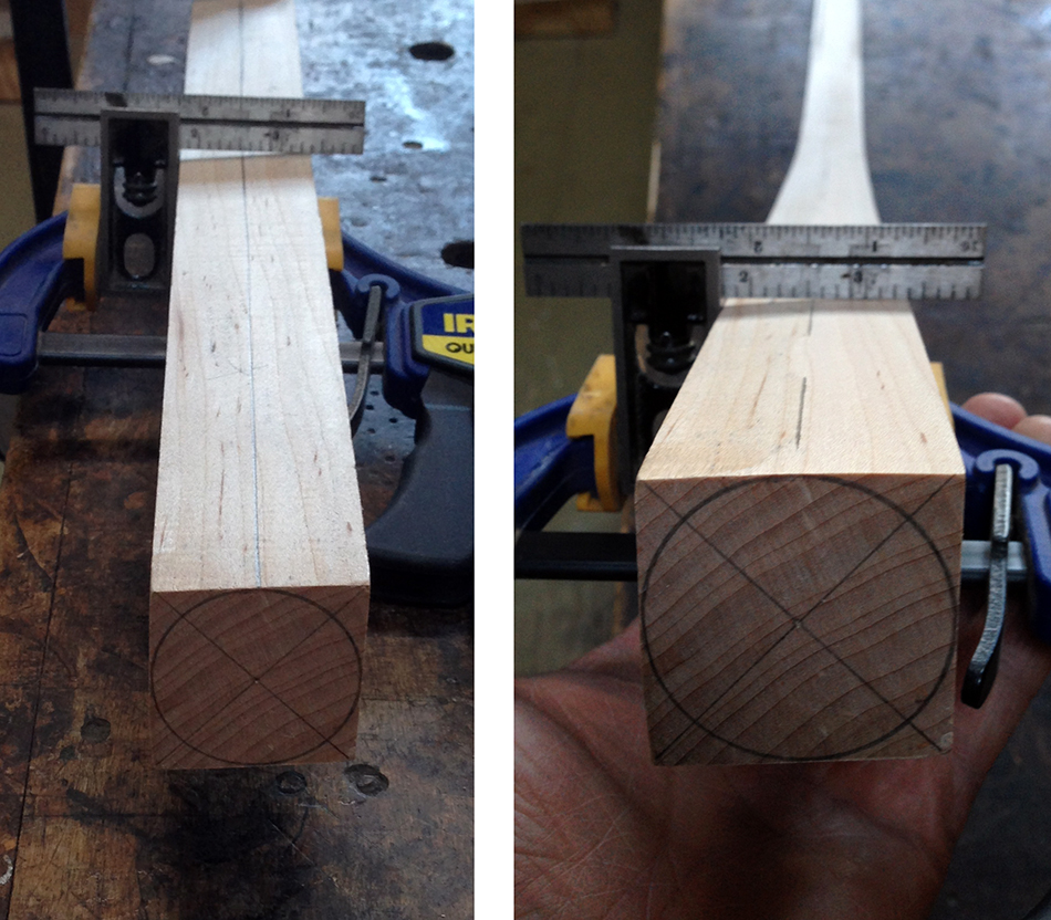
Pictured here is a cross section of the bottom of the twisted leg. You can clearly see that the sides are not square with the top and bottom. Because the ultimate shape of this leg will be round the out-of-squareness is not an issue, except when it is needed as a reference surface. On the right you can see that there is a full 1-5/8″ circle within the cross section. When I shape this leg from square to round I will be knocking off the corners leaving a true octagon and ultimately a true cylinder.

So, to get the twisted leg to work correctly in the holding jig I need to square up the two reference surfaces — the back and one side. In the left hand photo the square is held firmly against one side, but only touches the right hand edge of the back showing how much it is out-of-square. I need to preserve the thickness of the leg at the center (1-5/8″) so I must only square up the back of the leg from the center to the right edge. Using a spoke shave, I remove material from the right half of the back of the leg until it is square with one side as shown in the photo on the right. There is still a gap between the square and the back of the leg on the left half but that will not affect the fit of the leg in the jig.
Here is the twisted leg squared up and put back in the holding jig. Notice that there is no gap on the right hand side of the leg where it contacts the support block. This leg now fits correctly in the support blocks and is rotated to the correct angle. This means that the measurements I’m about to take will be accurate.

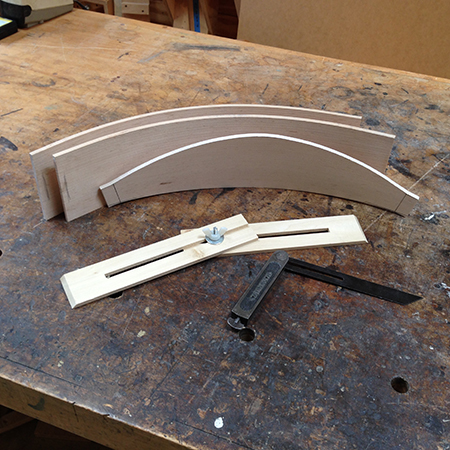
Here is a photo of both legs in the holding jig with the measuring jig in place to measure the distance between the legs at the top mortise as well as the angle for the slat tenon shoulder.

To get an accurate measurement place each arm of the measuring jig in-line with the mortise as shown here, and lock the two arms in place with the wing nut.
Before transferring the measurements from the measuring jig to the slat I first need to check the angle of the slat in the area of the tenons. Remember I have decided to rotate the rear legs 28°. In the finished chair it is the slat that rotates the rear legs, so the angle of the slat at the tenons must also be 28°. To begin I center the measuring jig on the slat and put marks at both ends where the jig touches the bottom of the slat. This represents the width of the slat at the tenon shoulders.
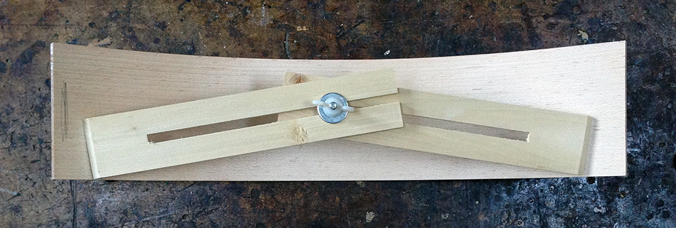
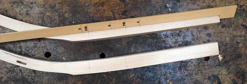
Then I add marks about an inch outside of each shoulder mark to represent the full width of the slat as shown here.

On a board I draw two lines at a 28° angle to the edge of the board. These angled lines are the same distance apart as the full width of the slat. I place the slat on the board lining up the outside marks with the angled lines. The object is to see if the outside 2″ of the slat are 28°.

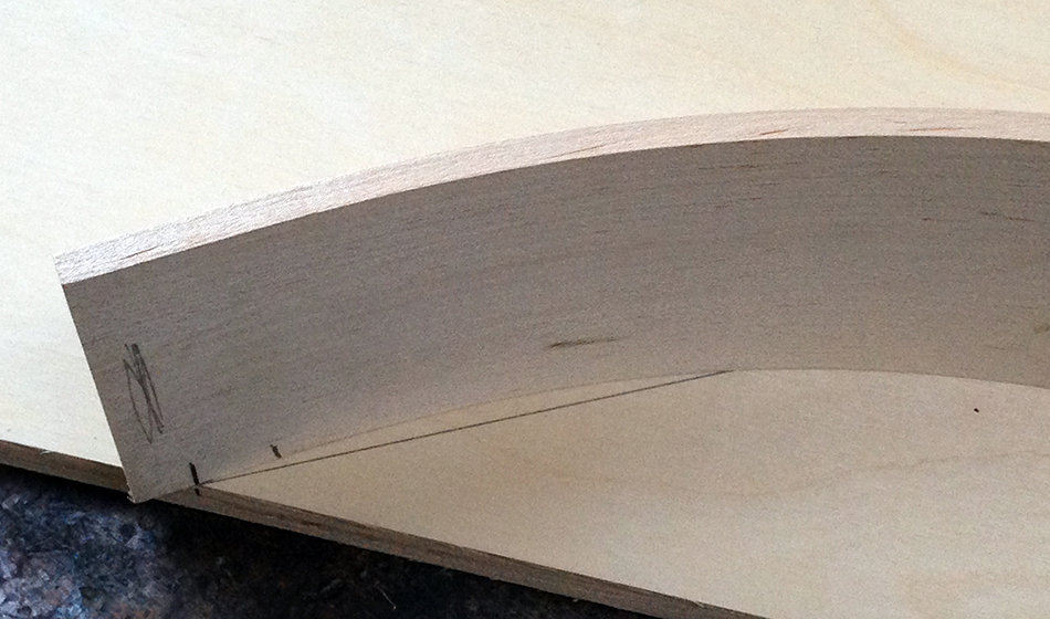
Here is a close-up of one side of the slat. As you can see, the angle of the slat at the outside mark is a good deal more than 28° so I will need to flatten the slat until the outside 2″ or so is exactly 28°.
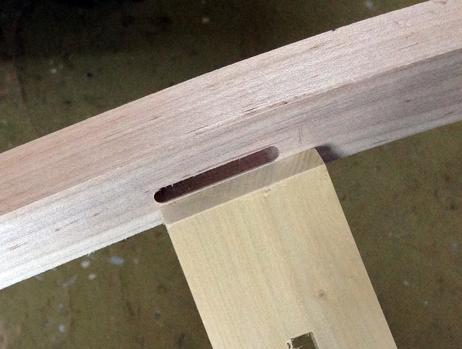
Here I have clamped a small block with a notch cut into it to the bench top. I put one end of the slat into the notch as shown. To flatten the slat I carefully apply downward pressure to the slat flattening the end in the notch. I repeat this with the opposite end of the slat then place the slat back on the board and compare it with the angled lines. I may have to do this several times before the slat matches the 28° angle. In some cases I also apply heat to the slat with a heat gun while I am flattening it. There are a couple of reasons for this. First, if there appears to be any chance that the slat will break, heating the area I am bending will help to prevent that. Also, I have had times where the slat just doesn’t want to get flat enough. Applying heat will help in that situation as well.

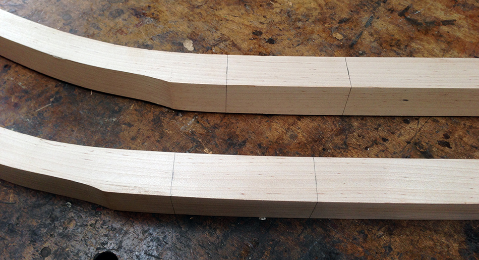
Here is the slat flattened to the correct angle. You can see that the last couple of inches of the slat match the 28° angle line. I’m now ready to begin laying out the shape of the slat.

I start by marking a line 3/8″ from the bottom of the slat at both ends. This is for the bottom edge of the tenon.
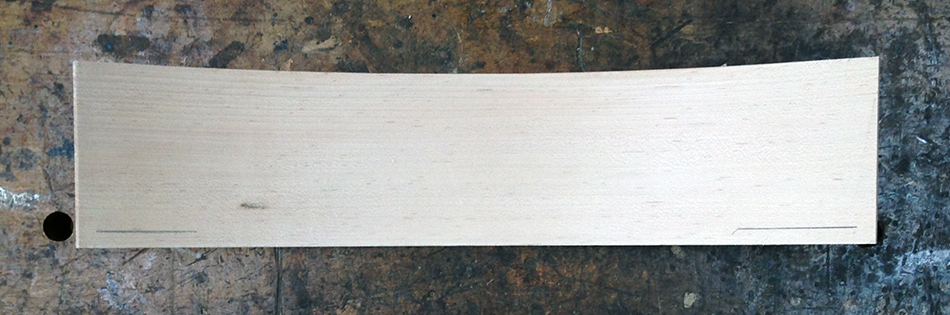
Next I lay the measuring jig on the slat with the bottom of the jig touching the 3/8″ lines. Then I strike line at the outside edge of each arm.

Here are the lines I just drew. They represent the shoulder of the slat tenon.
Before I go any further I need to check if the angle of both shoulders match. I set a bevel gauge to match the angle of one shoulder as shown below. Then I compare it to the angle of the opposite shoulder. Most of the time these angles match very closely. Occasionally they are off slightly — in that case I split the difference by changing the angle on the bevel gauge slightly. A large difference in the two shoulder angles indicates a problem and I’ll need to go back and check that I set the legs in the holding jig correctly.

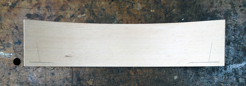
Once I have verified that the shoulder angles match or have adjusted the bevel gauge to compensate for slightly different angles, I extend the shoulder lines to the full height of the slat using the bevel gauge as shown here.
Next I add the width of the tenon by marking 3/4″ outside each shoulder line and drawing a second line on that mark, parallel to the shoulder line, using the bevel gauge. This line represents the outside edge of the slat tenon.
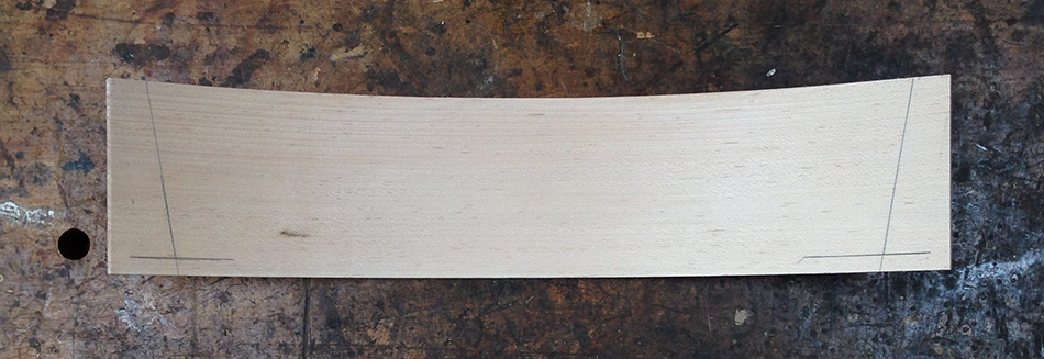
Now I’m ready to define the height of the tenon. Each mortise on this chair is a different height, so I go to one of the legs and measure the height of the top mortise, which is 1-5/8″. Beginning at the point where the shoulder line meets the line 3/8″ from the bottom, I measure up for the height of the tenon, in this case 1-5/8″. Then I draw two lines perpendicular to the shoulder line. The first is 3/8″ from the bottom and represents the bottom edge of the tenon. The second is 1-5/8″ above the first and represents the top edge of the tenon. The result is shown here — two tenons exactly the correct distance apart on the slat and with the correct shoulder angle. In the center of the slat I have also marked the top edge of this slat, which is 4" from the bottom.

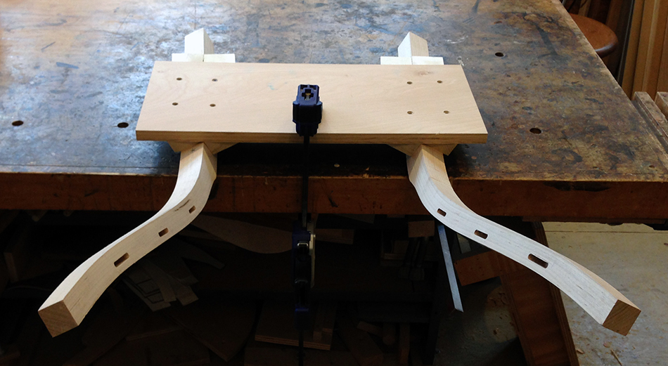
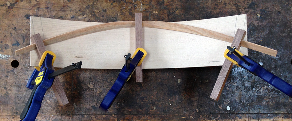
Next I need to connect the tenons with arched lines which will define the top and bottom edges of the main body of the slat. I will use a very thin strip of wood that I can bend between the tenon shoulders. This is easy to do with two people — one person holds the thin strip of wood at both tenons while the second person holds it down at the center and draws the line. If you have to do this alone you’ll need some clamps and a few scraps of wood with notches cut into them. I used the three sticks on the left with deep notches to hold down the thin wooden strip while drawing the top arc of the slat. The stick on the right with the shallow notch is used while drawing the bottom arc of the slat.

Begin by placing the thin strip of wood at the top center of the slat and clamp in place with one of the deep notched sticks. Next bend the arched strip until it just touches the top edge of the tenon shoulder and clamp in place with another deep notched stick. Repeat for the opposite side and draw a line along the bent wooden strip.
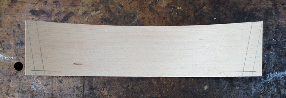
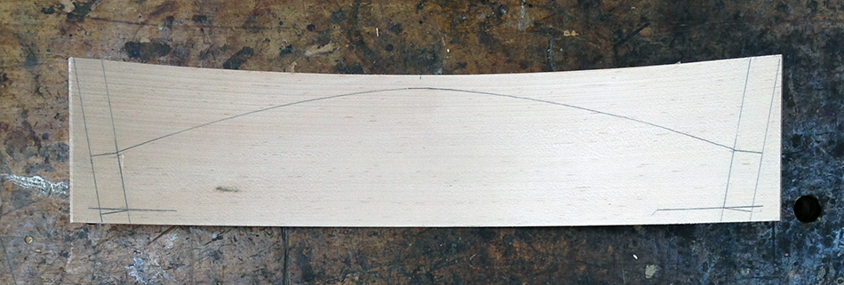
Here is the slat with the top arch drawn.
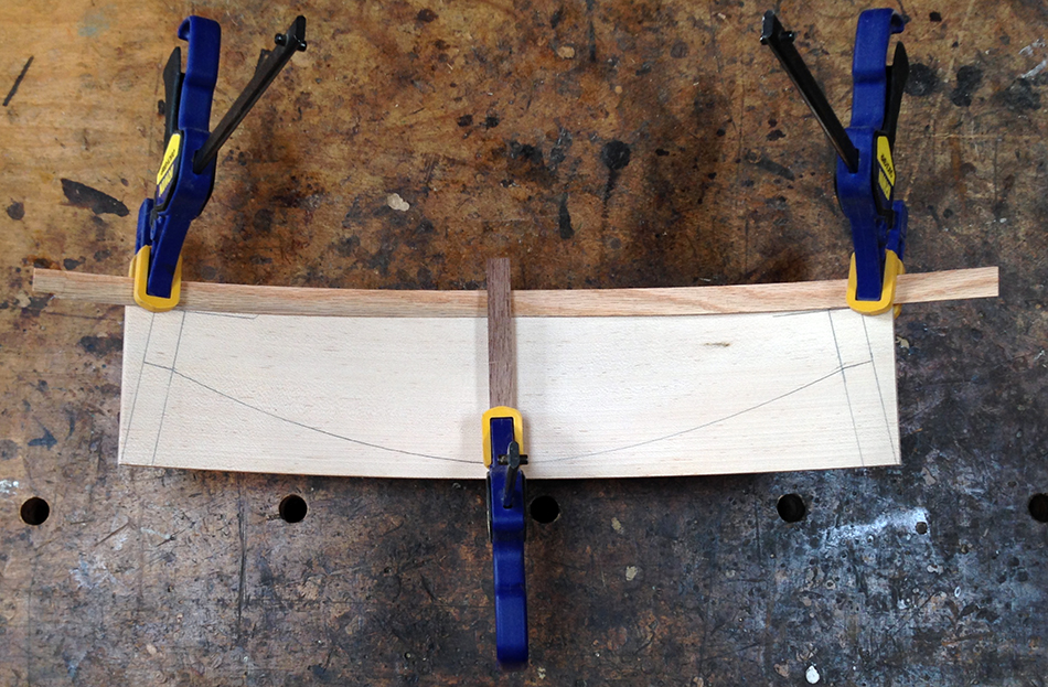
I repeat the process to draw the arc for the bottom of the slat. In this case I use one shallow notched stick in the center and clamps at each shoulder as shown here.
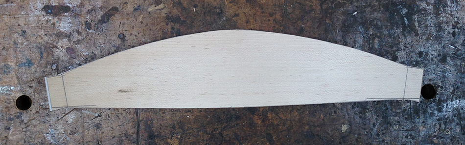
Here is the completed layout for the slat. I am now ready to cut out the shape on the band saw.

It is very important to preserve the outside edge of each tenon so I begin by very carefully sawing along the line.

I finish up by sawing along the top and bottom edges of the slat. I make certain to leave the line, especially at the tenon so that the height of the rough cut tenon is slightly more than the height of the mortise. When I fit the slat tenon to it’s mortise I will pare down the top and bottom edges of the tenon to fit precisely into the mortise. I also try to be as careful as possible to cut a pleasing arc on the top and bottom edges, but it does not need to be perfect at this time. When I do the final shaping of the slat I will fair out the shape of the top and bottom arcs.
At this point the tenon is slightly larger than the mortise. In the next post I will show you how I fit the tenon precisely to the mortise. The goal is to have the tenon fit perfectly the first time I dry fit it in the mortise.
Side Chair Build Series Links:
- Next Post: Fitting Slats, Part 3
- Previous Post: Fitting Slats, Part 1