Last time I described a method for laying out the slat mortises that aligns the mortises for the best possible comfort. In this post I will show you how to apply that method to make a slat mortising jig for use with a plunge router.
Layout the template
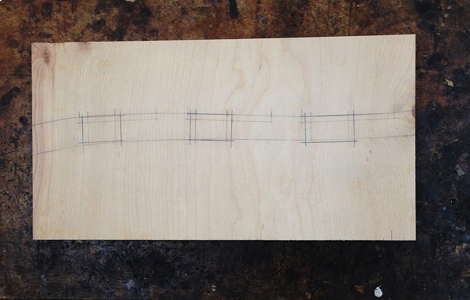
I begin with a piece of 1/2″ plywood or MDF that measures 9″ wide by about 21″ long. In the last post I showed you how to mark the mortise locations onto the rear legs. Using one of these rear legs, I begin by transferring the outline of the leg and the mortise locations to the template as shown here.

Here is the template marked with the outline of the rear leg and the slat mortise locations.

Next I draw the outside edge of each mortise. I want the mortises to be 1/4″ from the edge of the rear leg. But if I measure 1/4″ from the edge at the actual mortise locations I will end up with mortises that won’t align as well as is possible, especially in the relationship between the lower and middle mortises — see the last post for a complete explanation. The solution is to draw the outside edge of the mortise based on the full height of each slat at it’s widest point in the center of the slat. The bottom of each slat is 3/8″ below the tenon shoulder, so the first mark I make is 3/8″ below the bottom of the mortise location. From this bottom mark I add the full height of the slat and place a second mark. At both these marks I put a cross mark 1/4″ from the edge and connect them. The result is three lines, all 1/4″ from the edge, that form a continuous curved plane with each line pointing directly to the next as shown here.

Once I have the outside edge of the mortise drawn I can move onto drawing the inside edge which is parallel to and 1/4″ away from the outside edge. The bottom and top of each mortise is defined by the actual mortise locations transferred from the rear leg.

Here you’ll see the original outline of the leg, the mortise locations, and the final position of the mortises.

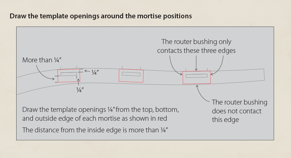
To complete the layout all that remains is to draw a template opening around each mortise. To cut the mortises I will be using a plunge router equipped with a 1/4″ straight cutting bit and 51/64″ outside diameter bushing (about .800″). The outside diameter of the bushing may sound odd but it is a standard size that is included in most bushing sets. The thickness of the slat tenons will be 1/4″ which the router bit will cut exactly. This means that the bushing only needs to contact three bearing surfaces to cut the mortise in the right location — the bottom, top, and outsides edges. The top and bottom of the template opening determine the length of the mortise. And the bearing surface on the outside edge locates the mortise relative to the edge of the rear leg. Based on the diameter of the bushing the bit will cut roughly 1/4″ away from the bearing surfaces. This means I need to layout a template opening 1/4″ outside the bottom, top, and outside edge of each mortise. The inside edge of the mortise is created automatically by the diameter of the router bit and does not need a bearing surface to reference to. So the opening on inside side edge needs to be greater than 1/4″ since the bushing will never touch that edge. I have been asked why not make the template opening exactly the same width as the diameter of the bushing. The main reason I don’t is that I don’t have the ability to machine the opening to that tight a tolerance. Additionally the bushing will tend to drag unless the opening is exactly the right size. With this setup I simply need to be careful to always keep the bushing against the long bearing surface along the outside edge of the mortise.
The backstop
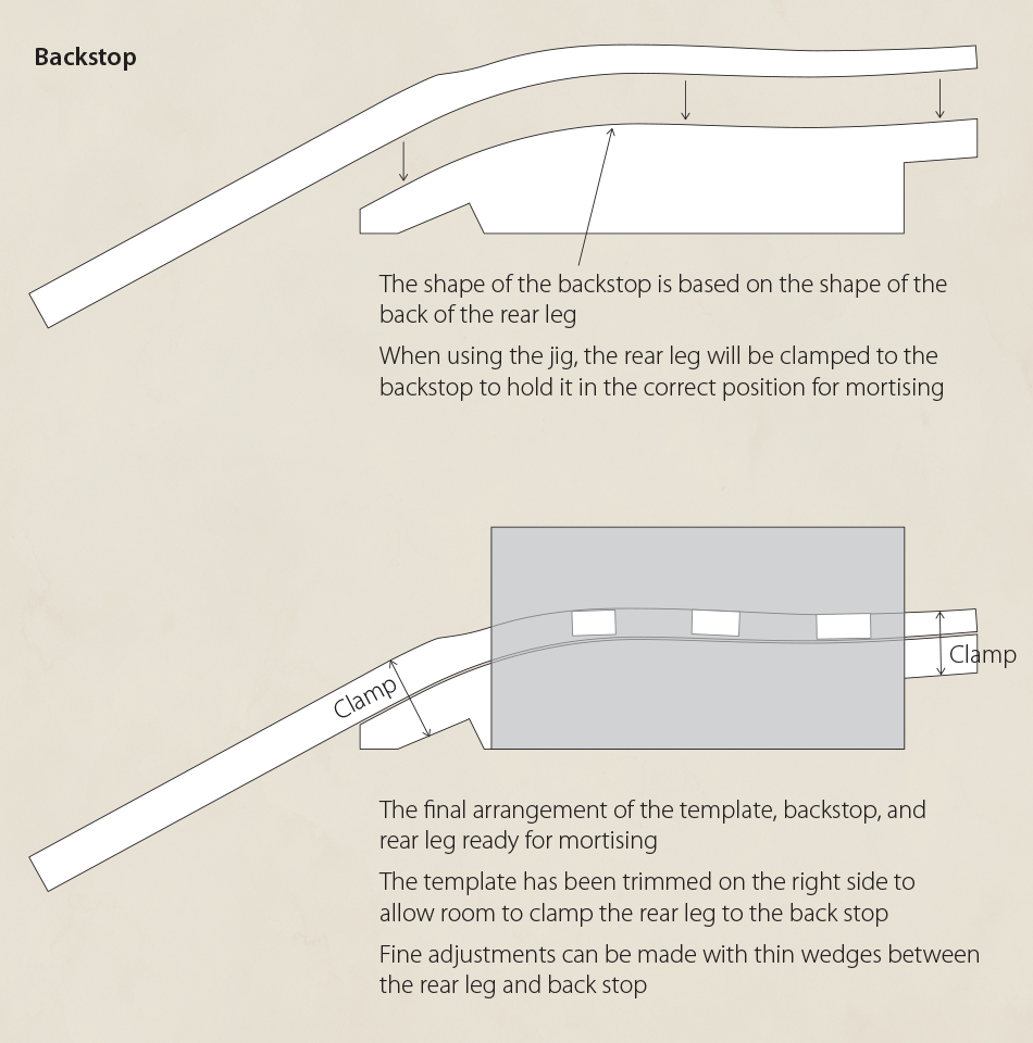
The other major component of the jig is a backstop to clamp the leg to while mortising. The shape of the backstop mirrors the shape of the back of the rear leg. The backstop is positioned on the template so that the template openings will cut the mortises in the correct places on the rear leg. Since there are often minor variations in the bend of the rear leg I can tap in thin wedges between the leg and the backstop to fine tune the position of the leg in the jig.
The jig
This should give you a better idea of the construction of the jig. There are two identical templates. One leg can be mortised in the position shown here. The jig is then flipped over to mortise the opposite leg. If you remember from the post on post-bend shaping of the rear legs, the final step was to cut a taper on the inside face of each leg. The tapered face is the side that receives the slat mortises. To hold the inside face tightly against the template while mortising I use a wedge with the same taper as the leg to support the leg from underneath.

Building the jig
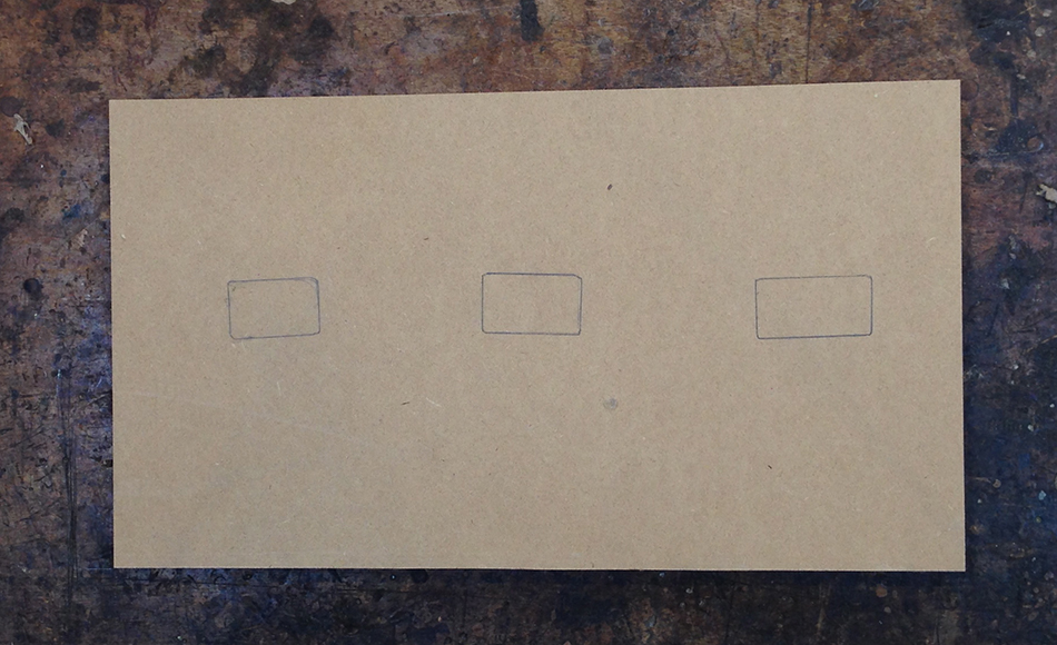
I begin by laying out the template openings on a piece of plywood.
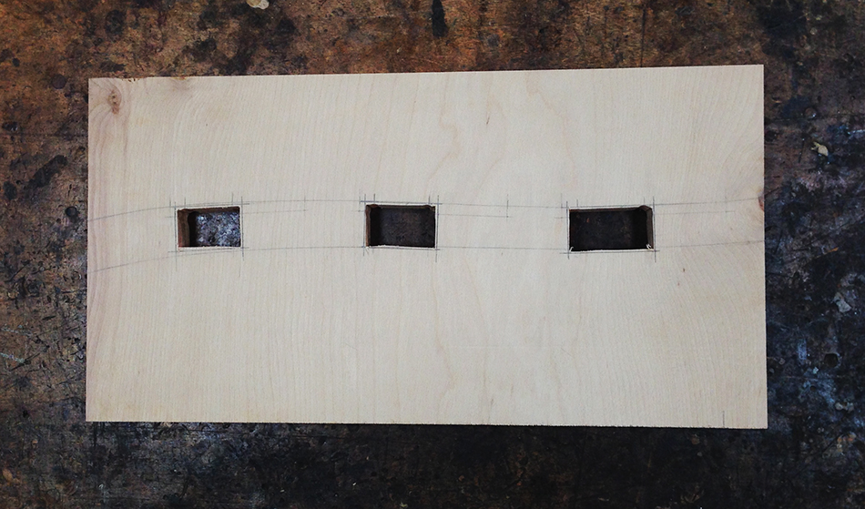
Then roughly cut out the openings to within 1/16″ of the layout lines.
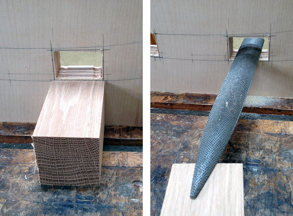
There’s a simple technique for filing exactly to a line. First I place the template in a vise and line up a small block of wood on the bench top with the layout line as shown on the left. To begin I place one end of a rasp on the block of wood and the other inside the template opening. To file I move the tip of the rasp and the wood block in unison on the bench top. The block keeps the rasp exactly perpendicular to the template and allows me to file very precisely to the line. I repeat this process for each side of the template opening and then for the other two template openings.
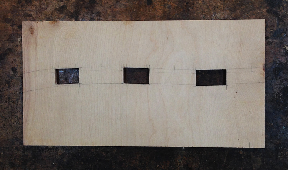
Here is the finished template. Each opening has been filed precisely to the layout lines. I will use this template as a master to rout duplicates for the final jig.
To make the duplicates I first transfer the template openings from the master to the duplicate.
Next I rough out the template openings by drilling 1/2″ holes in each corner and cutting out the waste with a jig saw.

Finally I screw the master to the duplicate and template rout the exact copy shown here.

Here you can see the backstop and three support pieces screwed to one template.
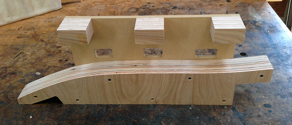
To complete the jig I screw on the second template. Both templates align at the lower right corner of the backstop so it is easy to align and assemble the parts. The final component is a wedge that is used to support the tapered leg and keep it flush with the template while routing. The angle of the wedge matches the angle of the taper of the leg — 5/8″ taper over 22″.

It seems like a lot of work to make this jig, but in reality it only takes a few hours. Once complete I can quickly and accurately mortise a pair legs. In the next post I will show you how I use this jig to cut the slat mortises in the rear legs.
Side Chair Build Series Links:
- Next Post: Slat Mortising, Part 3
- Previous Post: Slat Mortising, Part 1